I had always wanted to try and receive a signal from a satellite using my scanner. After some research I found that I may actually be able to pick up the NOAA Weather Satellites as they pass overhead.
Now, during normal operation of my scanner, it is usually just hooked up to my TV antenna which is affixed to the roof of my two story house. For normal operation, I’ve actually found this to work quite well. I’m able to pickup pretty much anything I’d like with reasonable quality… Except for the NOAA Weather Satellites.
Using the setup described above, believe it or not, can work… Not well, but, it can… The thing is, conditions need to be just right. The TV antenna is a highly directional piece of hardware which is pointing toward Green Bay where most of the TV broadcasts are located. In order to receive ANYTHING of quality a satellite would need to be located in the sky exactly where my TV antenna is pointed. This only happened once and I was able to receive a pretty good image for about 5% of a satellite pass. Pretty exciting considering my very standard setup! But, I wanted more!
It had been about a year since I last looked at trying to get something better and after some research I found that an excellent antenna for picking up these signals are Quadrifilar Helix Antennas (137 MHz). There are plenty of plans online for building these antenna, but again as with most instructions online, I found them to be incomplete and not answering some of the questions that I had. A lot of plans online seem to assume some type of basic knowledge which I just seem to lack. One of the main reasons I like to document the way I do the projects and post my results… good or bad.
The design below is based heavily on George Goodroe’s (KF4CPJ) design. Some Googling will reveal a couple projects done by people recreating this antenna. My hope here is to add to the content available to help others build these excellent antennas and hopefully answer some of the questions I had as well. The link above lists pretty much all of the materials needed.
| I placed the cap on the PVC to see where I can drill my holes for the copper tubing and drew a line. I can now drill my holes below this line and know the cap will fit after the copper tubing is installed. | 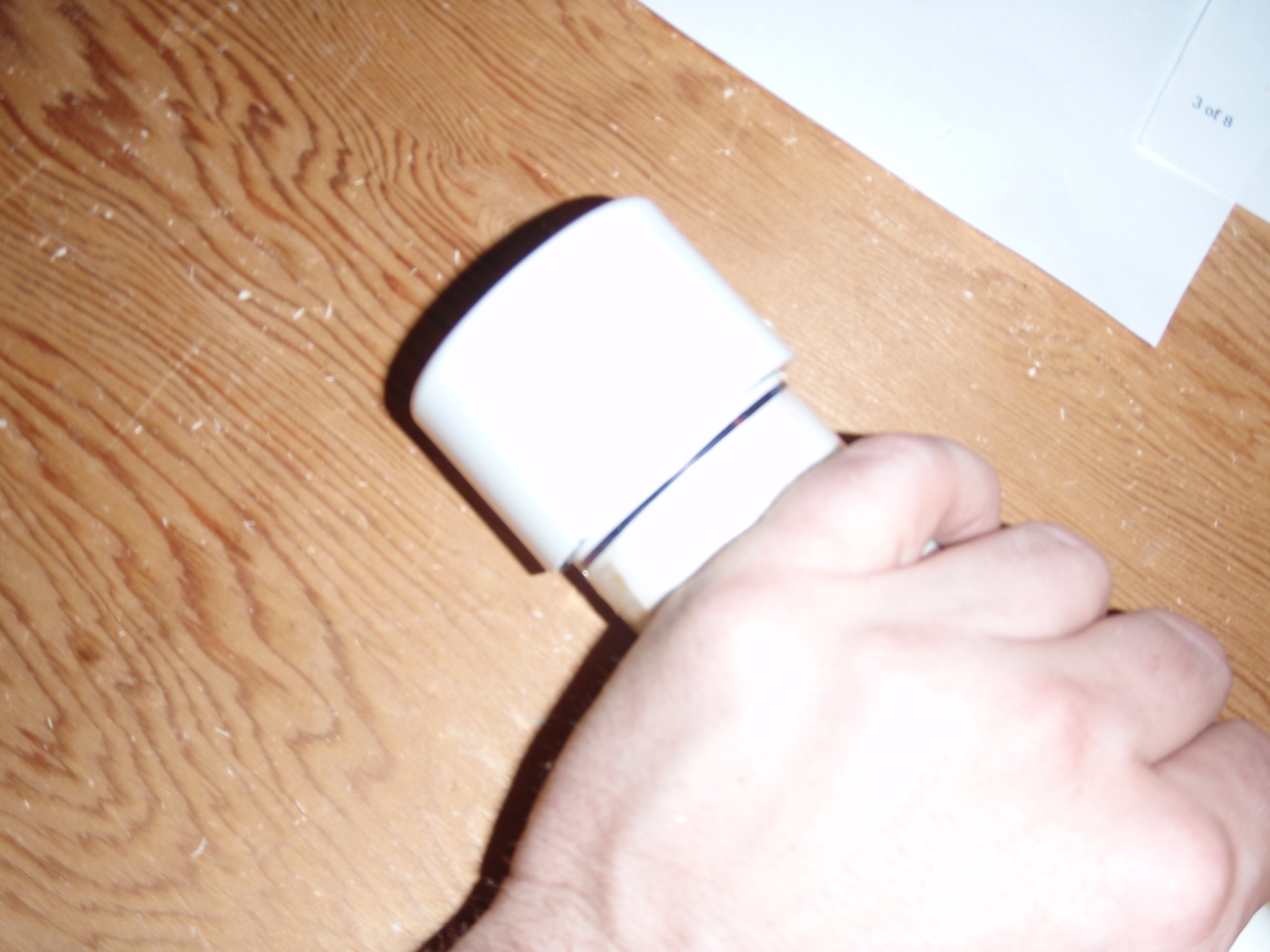 |
| I measured the circumference of the PVC. I will then divide by four in order to find where to drill the holes. Drilling the holes by the naked eye just didn't cut it for me. They were way off! I guess it's hard to judge these things on rounded surfaces! | 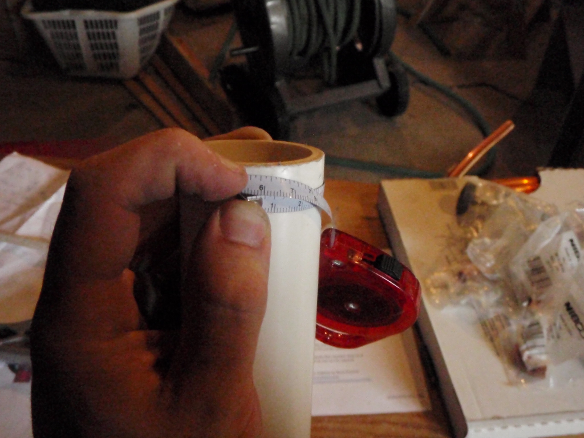 |
| Using some standard scotch tape I marked the length of the diameter as well as each 1/4 (This gives us our 90 degree angles after applying the tape to the PVC). |  |
| Now I applied the tape to the PVC. I aligned the side of the tape without the dots to the line from the PVC cap drawn earlier matching up the 1st and 5th dot. This makes sure there is enough room for the copper tubing after the cap is on. | 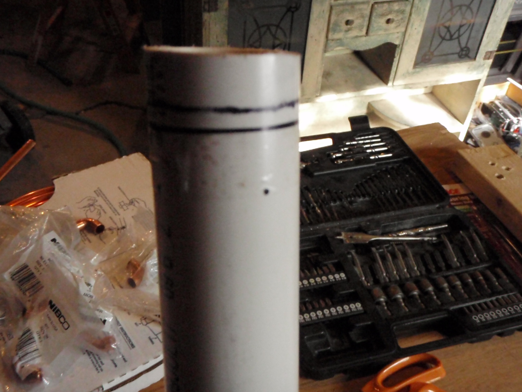 |
| I now drilled the four holes for the PVC. I found a boring bit that was just slightly (not much) bigger than the copper tubing because I didn't want to fight the tubing. I would have done this differently. I should have chosen the exact size boring bit or maybe even a little smaller. This would keep the smaller pipes from moving around. Also I drilled these with a hand drill. I don't have a drill press, but if you have one I would recommend using it. | 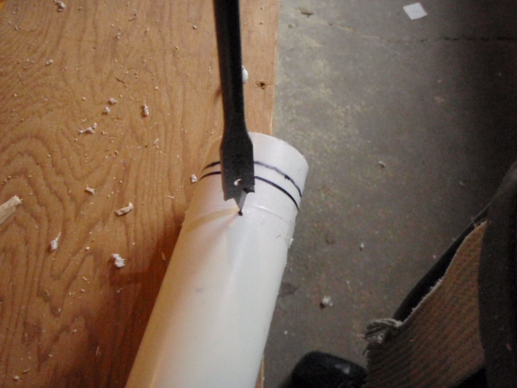 |
| Using a straight piece of lumber I made some marks indicating where the bottom four holes should be. Since I knew the top four holes are at 90 degrees I lined the lumber up with the holes and was able to mark the bottom holes exactly where they needed to be. Remember, that there are two pipes longer than the other two and they should be opposite of each other. (The same lengths should be 180 degrees from one another) |  |
| Just matching up the marks I made in the previous step. These bottom four marks where then drilled. | 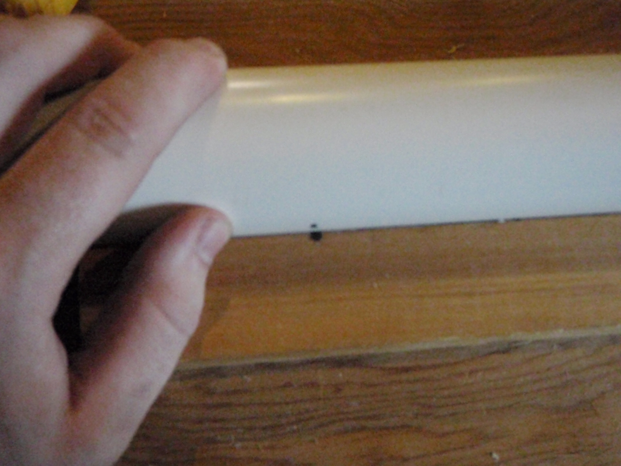 |
| I bought the copper tubing that comes in a box. So it is all in stored in spiral. Before working with it, I made to straighten it out by hand. Once it was straight I measured and cut all my pieces. | 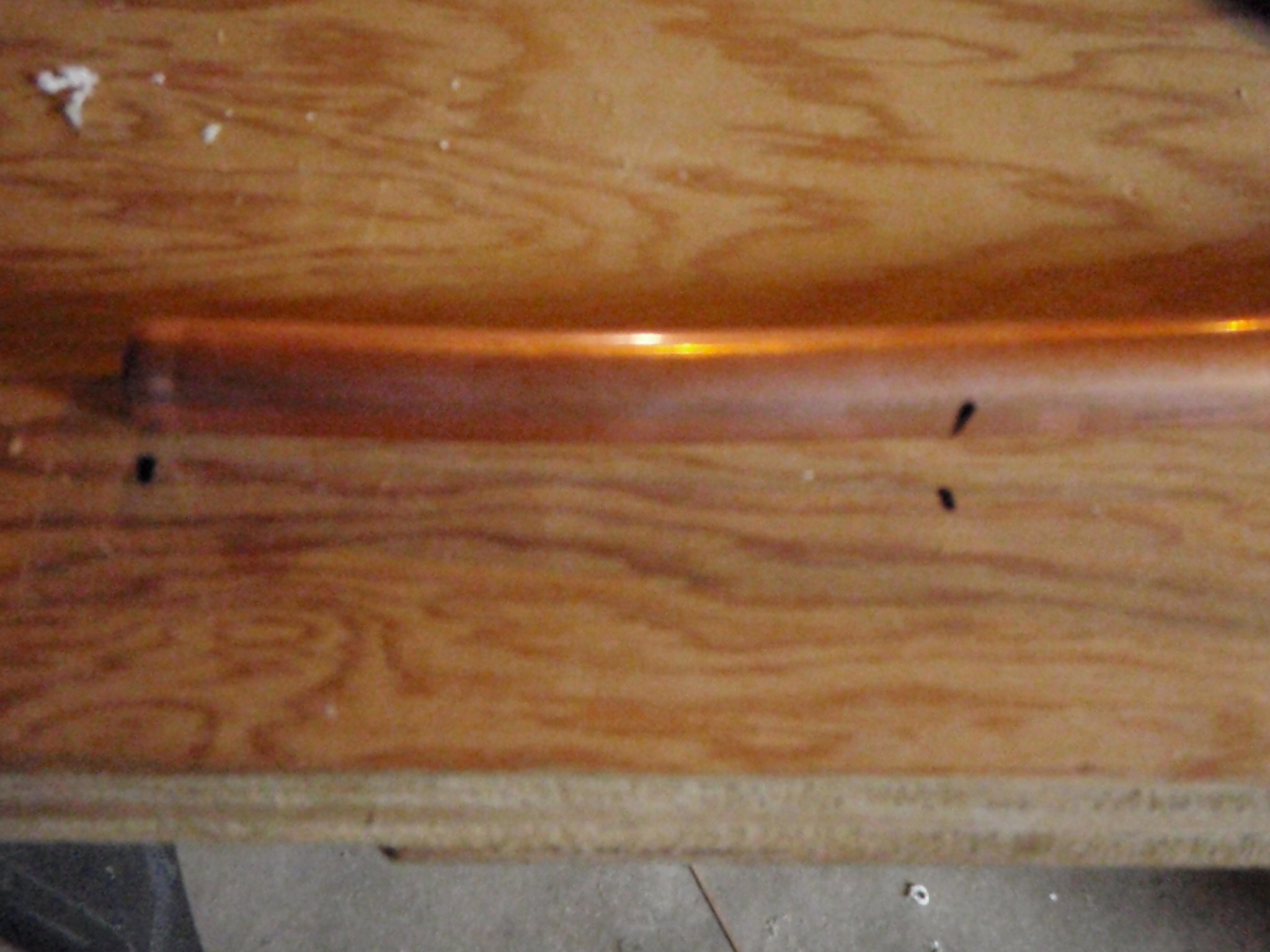 |
| I cut all my tubing using a pipe cutter. I lined up the blade on the lines and tightened the blade gradually. While cutting the tubing I tightened the blade about 1/4 - 1/2 a turn per revolution. | 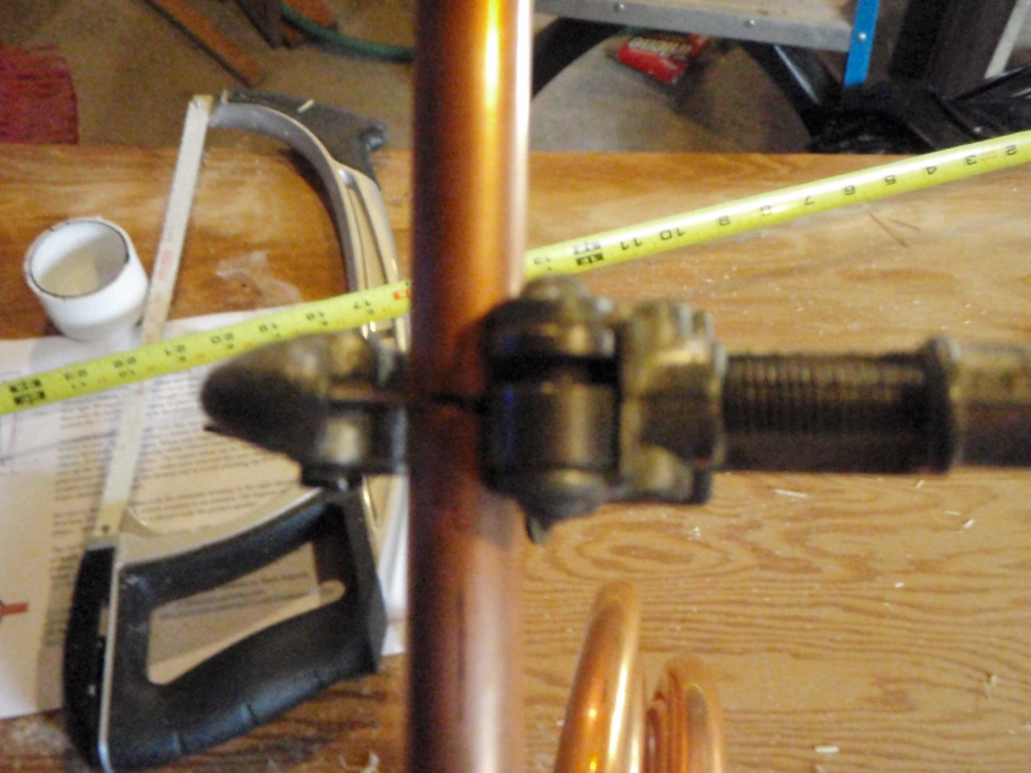 |
| For the top four pieces where the coax will be connected I drilled some holes for the screws. This would have been MUCH easier with a drill press and the correct drill bit. But, I make due with what I've got. |  |
| I then drilled a hole and installed the coax. This stuff is always a learning process. I strongly recommend waiting on installing the coax. Drilling the hole is enough for now. | 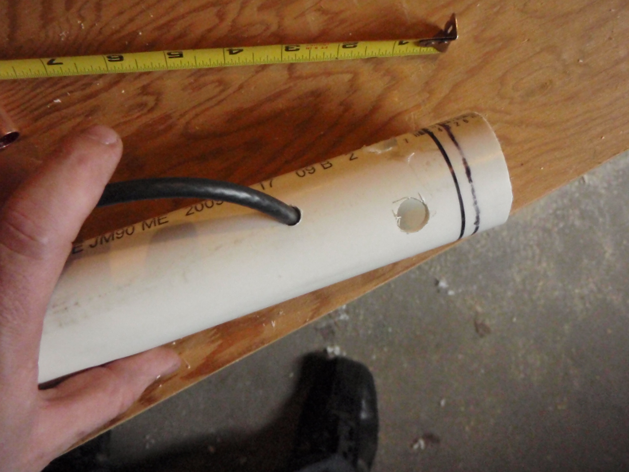 |
| I then connected the followed the wiring diagram found online and wired up the inside. Again... I would wait on wiring this stuff up for now. All the twisting a torquing of the long pieces put a lot of stress on the wiring and I ended up redoing the wiring anyway. |  |
| Here is a higher quality image of the wiring diagram. I found the others online to be difficult to read. As with all these pictures, If you click on the image you should get a larger image. | 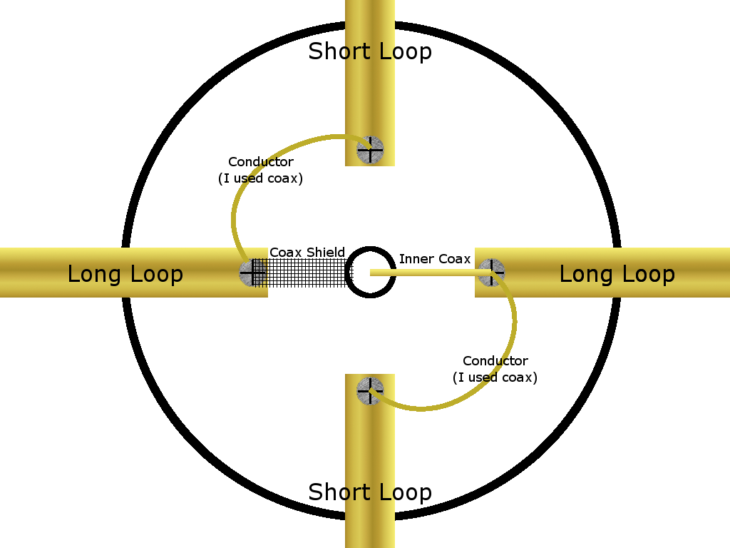 |
| Wrapped the coax four times. | 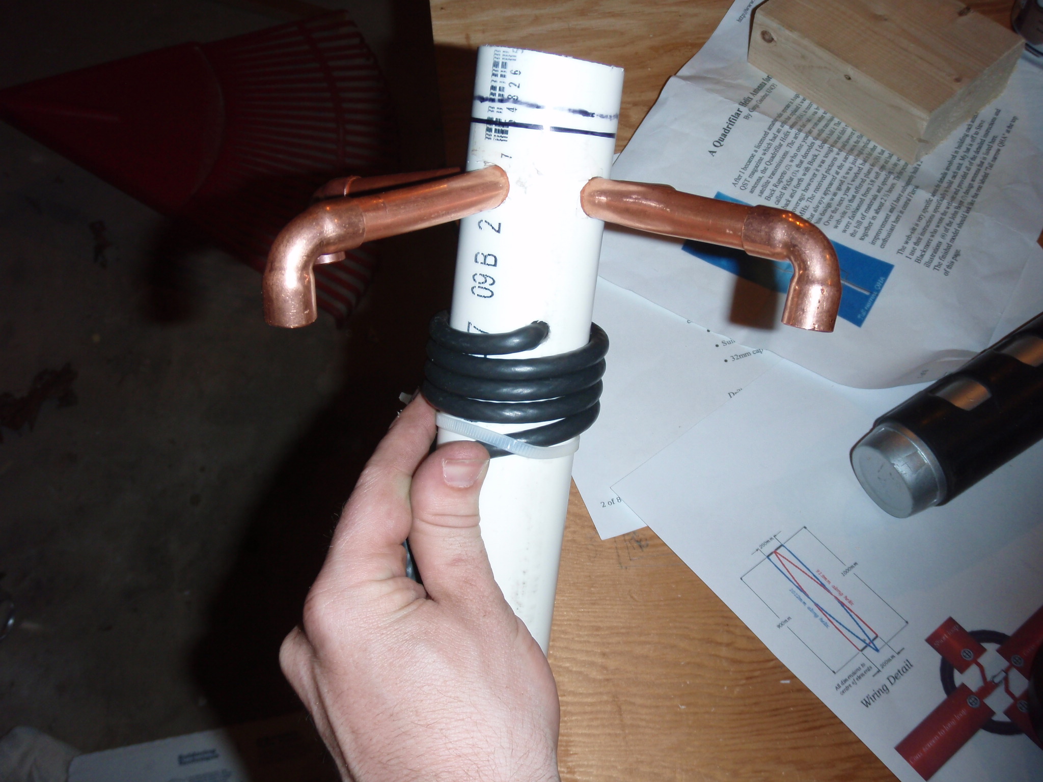 |
| I now had to bend the longer elements to make the 180 degree bottoms. I wish I could give some good advice on how to do this better. Some people say to use a large barrel or log... I had neither. I ended up doing these by hand as accurately as possible. In the long run they turned out ok... But not great. It was the most difficult part of the build. |  |
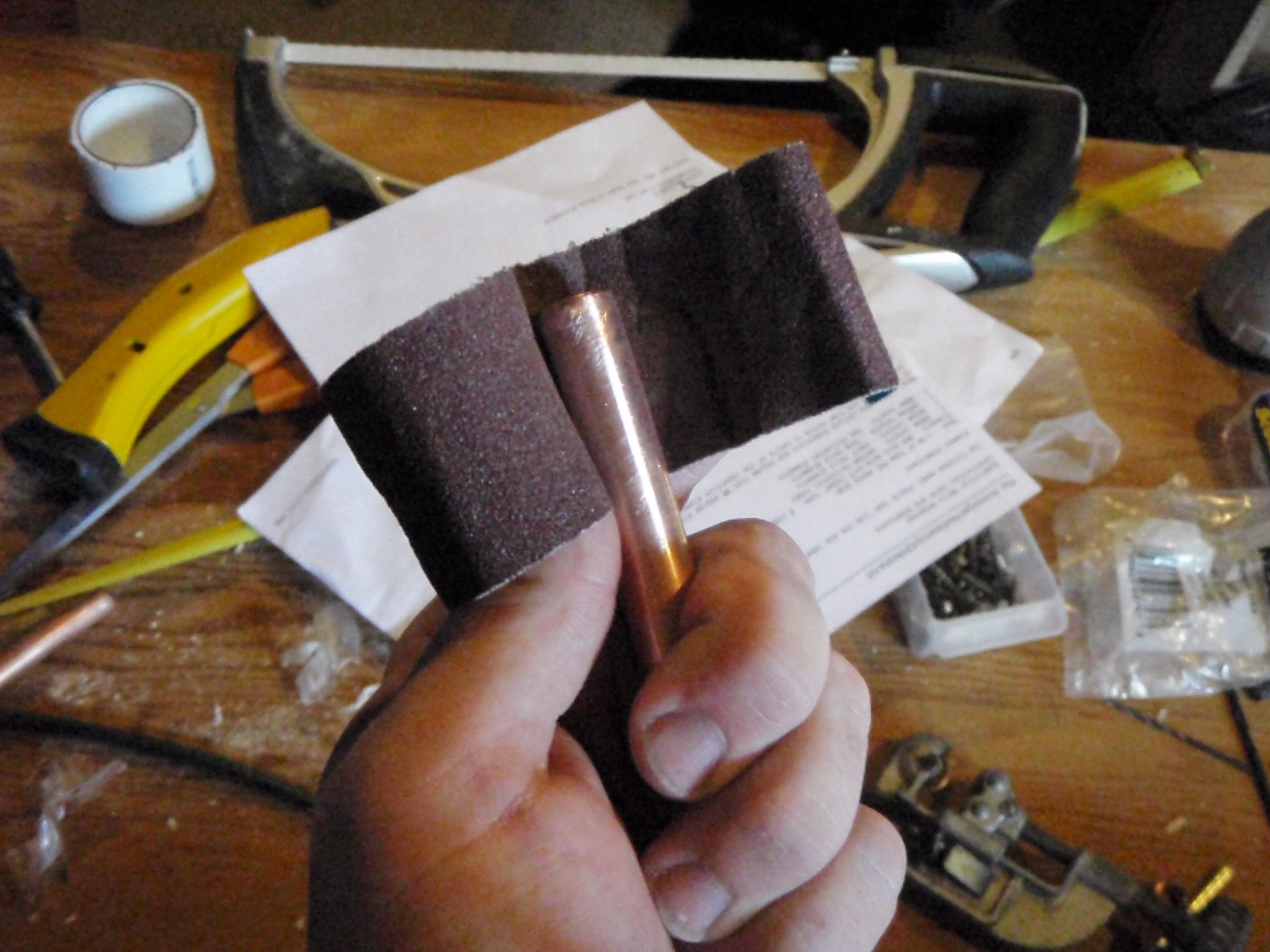
| Once I had an element dry fit I made sure to make it permanent because this antenna will move around a lot while you dry fit the other pieces. To do the joints, first I sanded each male piece of the copper using plumber's sand cloth until they were shiny. | |
| Then using a wire brush (which I'm not sure they make a wire brush for the size we're working with) I brushed the insides of each piece. | 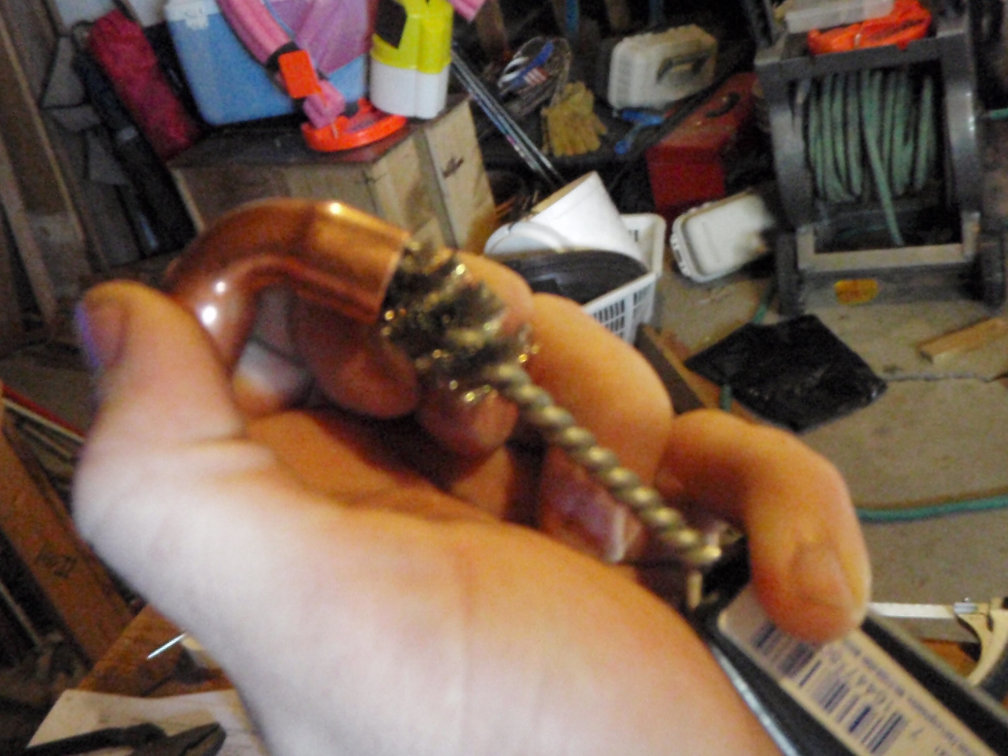 |
| Then using a flux brush I applied plumbers flux to the male and female parts of the tubes. | 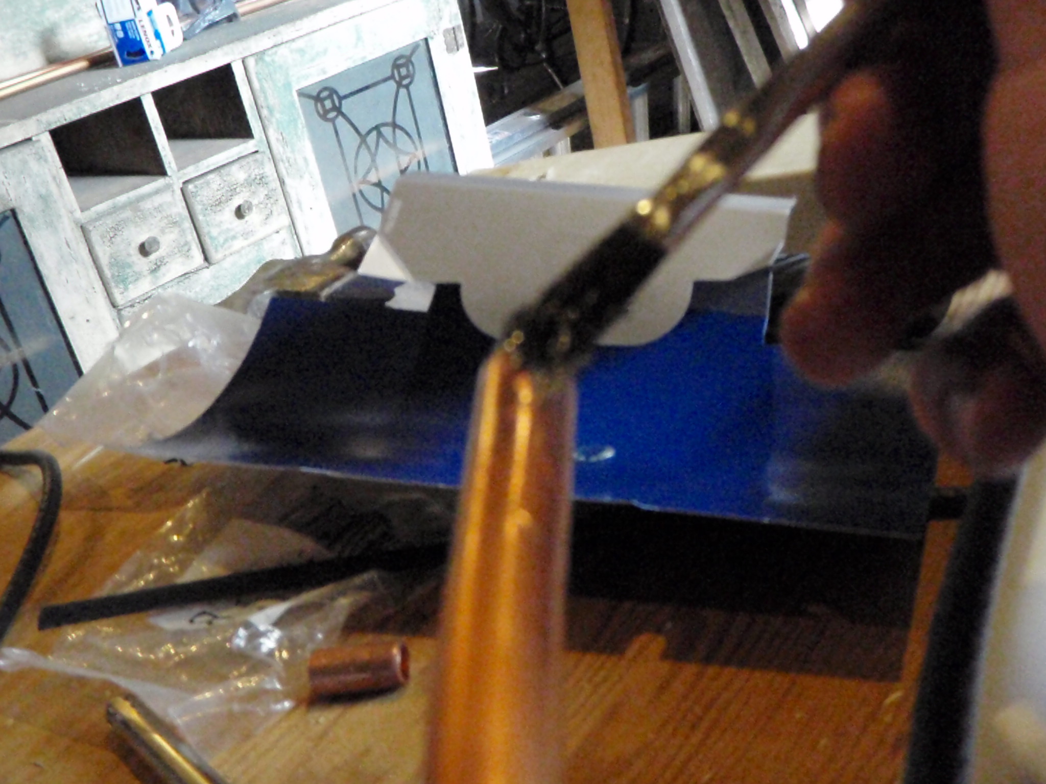 |
| Now I inserted the pieces and used a blow torch to heat up the fittings. | 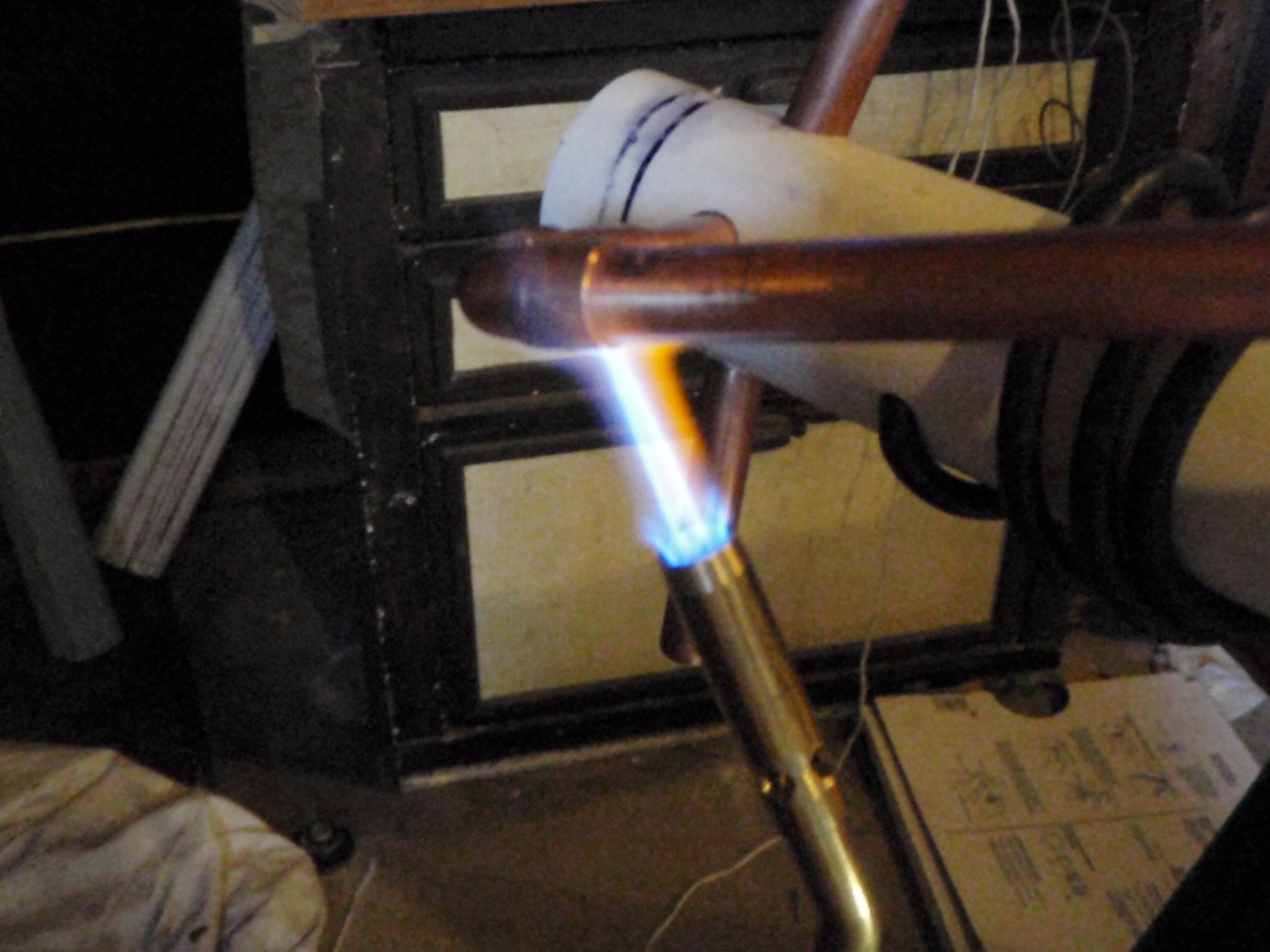 |
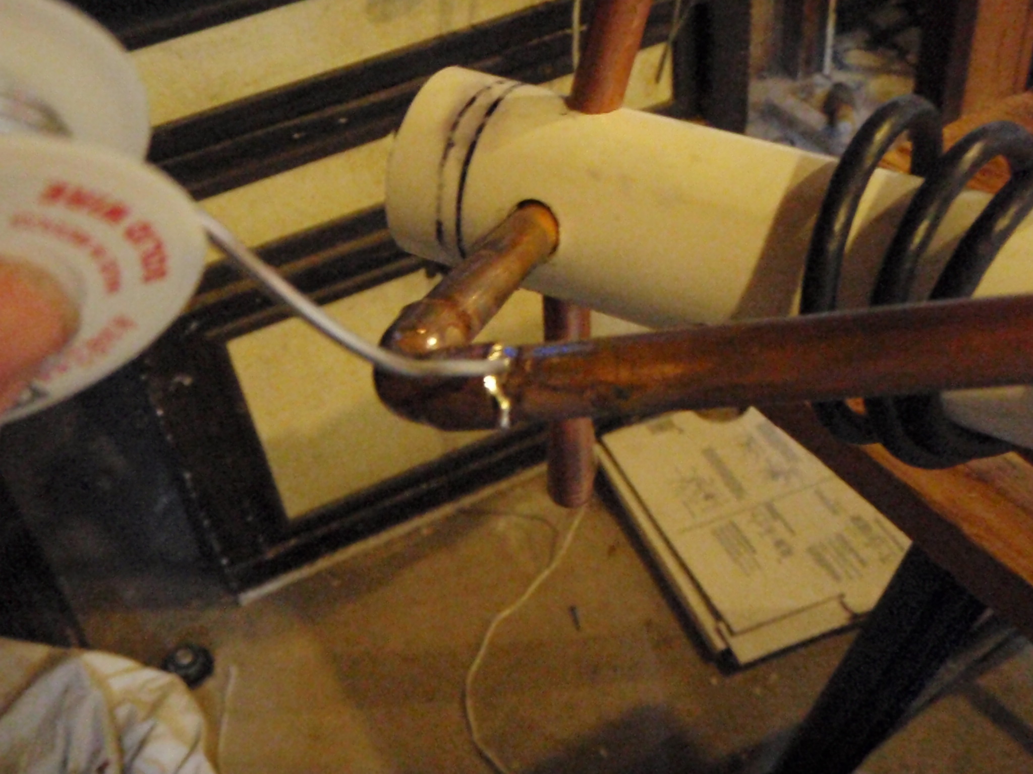
| Once heated up I applied the solder. The solder will get "sucked" into the fittings. It's done once the solder starts falling out of the bottom, so always apply to the top of the fitting. Since we're not actually pumping water through these, they don't need to be water tight. They don't need to be perfect. | |
| After doing that to all the pieces and wiring it up, this is the completed QHA antenna... For those detail oriented types... yeah, In all the excitement of completing it I forgot to put the PVC cap on top. :) | 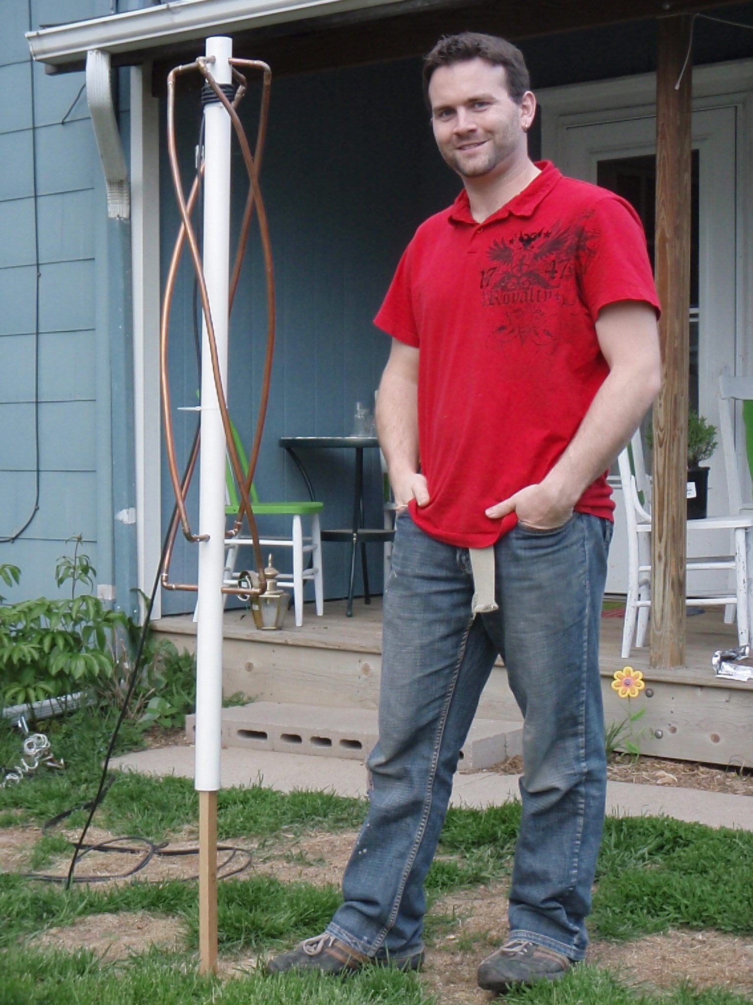 |
| Here's my Uniden Bearcat BC780 XLT scanner receiving from NOAA-15. On a side note, NOAA-15 seems to come in quite well with this antenna! Also, I have slightly modified my scanner with a discriminator tap to bypass any audio processing the scanner applies to the signal. | 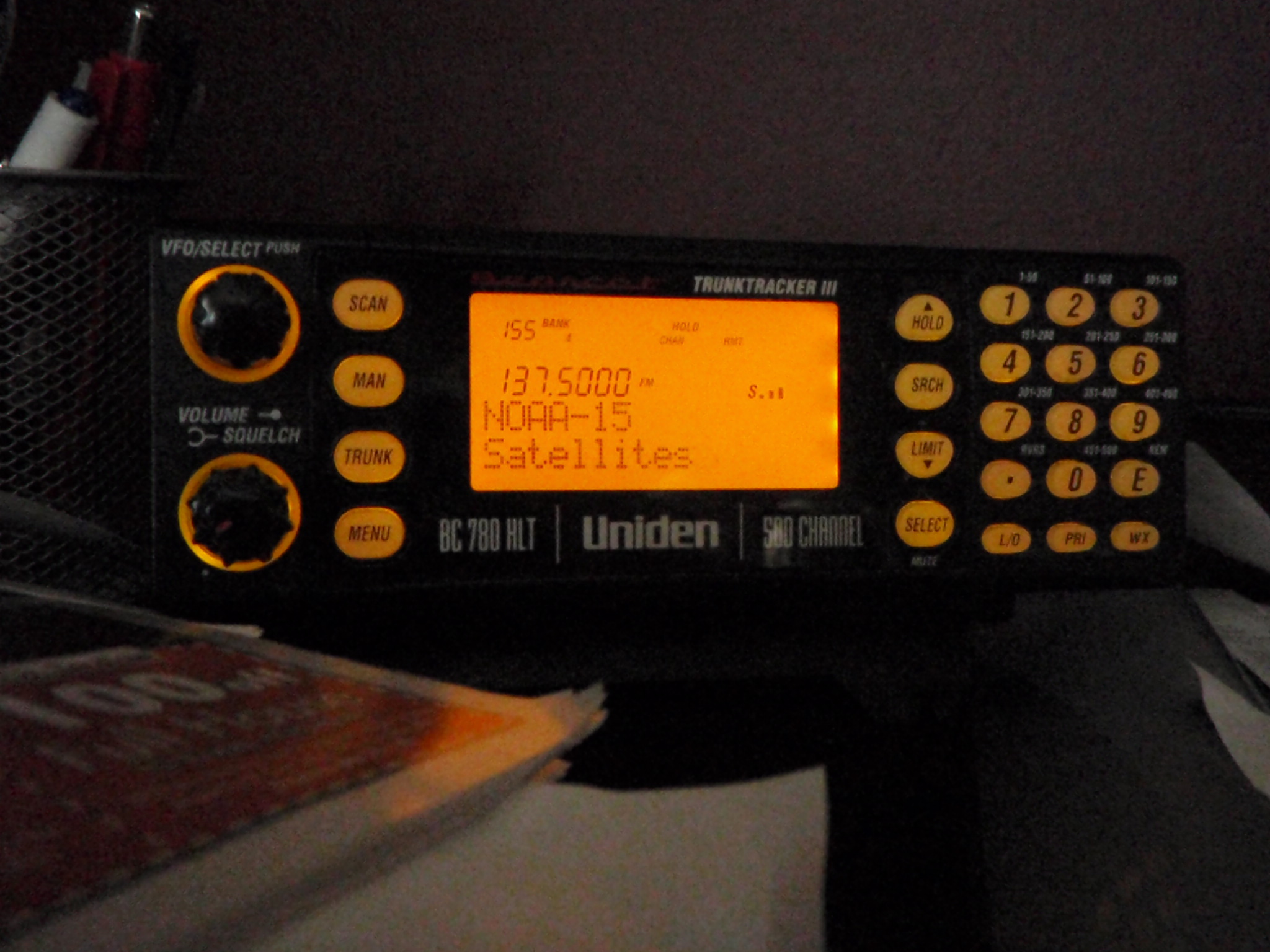 |
| My computer on my messy desk decoding the signal from NOAA-15. Here I am using the free version of WXtoIMG. In my experience does A LOT better processing on the signals. The quality is even higher using this software than other software packages out there. | 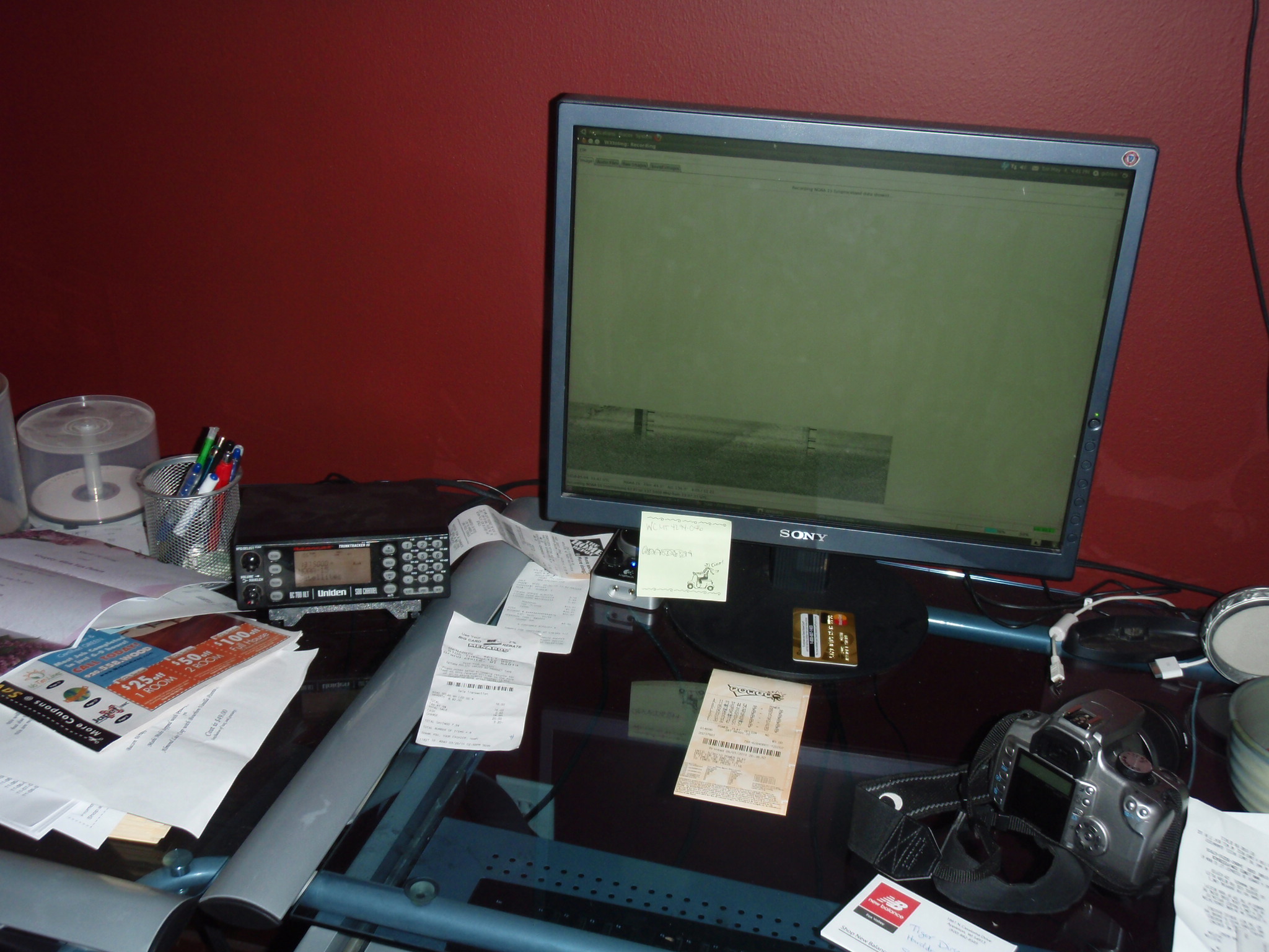 |
| Here is my first reception using the antenna. I've received MUCH BETTER than this as well! Interestingly enough, the storm system you see approaching Wisconsin actually produced a tornado just a couple miles from my house that night. |  |

